Overview of features and benefits
Measurements
- Optical, non-contact, non-destructive
- High speed: Up to 100,000 3D point measurements per second
- 2D and 3D surface and subsurface characterization; diameter, circularity, cylindricity, runout, taper, distortion, straightness
- High-aspect-ratio features: undercuts, threads, grooves, cross-holes
- Sub-micron resolution and excellent sensitivity and measurement repeatability
Imaging
- Line profiles
- 3D images of internal and external surfaces
- Height and intensity images of “unfolded” surfaces
- Cross-sections of semi-transparent materials
- Deviation maps
Benefits
- Easily integrated in lab, shop, or fully-automated inspection setups.
- Reduces inspection cycle time: up to 100,000 measurements per second are obtained, each representing a 3D topographic point
- Flexible options for evaluating inspected parts: measured features can be compared to CAD drawings or to a user-defined set of locations, nominals, and tolerances
- Simple scan definition and execution: The scanning sequence is defined once by teaching the system with a joystick. The scanning sequence can later be executed with the push of a button.
- Time-saving automated reporting: Following a scan, go-no-go reports can be produced, and results logged in a manner compatible with industry-standard mechanisms
- Easy part handling: The part fixture is selected to make handling easy and to ensure good repeatability
- Adaptable to harsh environments
- No consumables are needed: Optical probes do not come in contact with the measured samples, and therefore do not wear out like contact probes. Accidental damage is rare−probes are designed to be rugged.
Metrology applications
3D metrology and imaging of tubes for industry and R&D
- Quality control
- Automated 3D production inspection, geometric dimensioning and tolerancing (GD&T)
- Statistical process control (SPC)
- Research and development (R&D) inspection
- Reverse engineering and part-to-CAD
- Maintenance, repair and operations (MRO)
- Profilometry in hostile environments: radioactive, cryogenic, very hot
Typical measurements on tube ID/OD
- Full 3D geometry, diameter, circularity, cylindricity, taper, runout, etc.
- Deviation from CAD model, GD&T
- High-aspect-ratio features: undercuts, steps, O-ring grooves, threads, channels, sharp edges, steep slopes, and cross-holes
- Volume loss: surface wear or other damage
- Defects: corrosion, pitting, cracking, denting, scratching, porosity
- Surface roughness: linear or area roughness
- Thickness of semi-transparent coating: single-layer or multilayer films
Examples of tube inspection applications
Measurement, visualization, and inspection of ID and OD surfaces of:
- Various tubes, pipes, and shafts in the aerospace and automotive industries
- Example from aerospace: jet engine shaft MRO (maintenance, repair and operations)
- Examples from automotive: drive shafts, axles, threads, splines, gears, drive teeth
- Vials, cylindrical containers in the biomedical and chemical sectors
- Cylindrical devices in the medical sector
- Examples from defense industry: barrels, bores, reamers, mandrels, drill bits, die blocks
- Tubular parts in high-precision machining, drilling, injection molding, 3D printing, additive manufacturing, casting, extrusion dies
- Composite tubes and rods
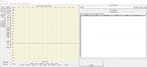
System Software
The TUBEINSPECT system comes with NOVACAM high-performance data acquisition software,, which is PC Windows®-based and user-friendly for scan programming.
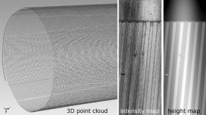
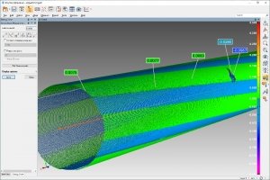
The system simultaneously generates 3 data sets from the same scan:, 3D point cloud, light intensity image, and height image. The height and light intensity images facilitate defect detection. STL file format is also available.
For full GD&T analysis of measured parts, a turnkey solution is available with PolyWorks InspectorTM, metrology software that may be purchased with the system.
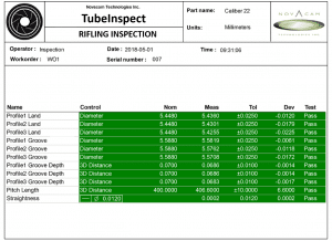
- Go-no-go reporting is easily programmed and automated.
- Users benefit from capabilities such as a quick visual comparison (deviation map) of the acquired part measurements to pre-specified tolerances or to the CAD of the part.
Visualizing the scan data may be accomplished by importing the data into various third party visualization and numerical analysis software, such as PolyWorks Inspector, Geomagic, ImageJ, SolidWorks, Octave, MatLab, Mathematica, IDL, or IGOR Pro.
Deriving application-specific measurements from the 3D point cloud is available through a selection of in-house and third party software. Novacam supports the following options:
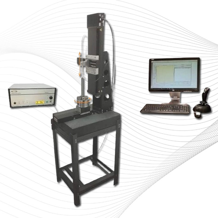
Standard system configuration
A standard configuration of the TUBEINSPECT system includes:
- MICROCAM-3D interferometer
- 1 standard 4.6 mm-diameter side-looking probe (for inspection of bores up to 600 mm (24″) deep)
- 3-axis inspection station and 3-axis motion controller
- 1 chuck with motor and motion controller for rotating the inspected tube
- PC with NOVACAM acquisition software
- 1 year warranty
Standard system configuration
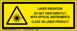
- MICROCAM systems feature an in-probe red laser pointer (650 nm wavelength) for alignment purposes.
- MICROCAM systems are Class 1M Laser products, with < 20 mW of infrared and < 5 mW of in-probe laser pointer.
- Scan time depends on the tube size, tube length, what aspects of the tube you need to measure, and the rotational speed of the stage (chuck) holding the tube. The TUBEINSPECT system(with MICROCAM-4D) acquires up to 100,000 measurements per second, which represents 1 million 3D topography points in 10 seconds. Standard speed of part rotation is 2 rotations per second. The speed can be higher depending on the application (e.g., depending on tube size, weight, and related safety factors). The user selects the rotation speed, the probe acquisition speed, and the pitch of the spiral, which together determine the number of points that will be acquired and the time the scan will take. In general, dimensional measurements (for GD&T) require the least amount of points and can be achieved the fastest. Roughness callouts may take 3 to 4 seconds each. Defect detection requires the most amount of points, of course depending on the size of defect you are looking for. For help with estimating the time required to scan your tubes or cylinders, please contact us.
- Yes, depending on the geometry of the cavity. Note that if the workpiece containing the cavity cannot be rotated (i.e., it needs to remain stationary), you may want to consider using the BoreInspect system, which comes with a rotational scanner, which quickly spins a side-looking optical probe.
- Yes. The scanning sequence (recipe) can be programmed with a joystick and can be recalled at later times with the push of a button.
- Yes. The system is ideally suited to both lab and shop floor inspection. Inline and robot setups are an option. The non-contact probes can even be configured to work in hostile environments such as extremely hot, cryogenic, or radioactive.
- Yes.
- No, runout is not an issue with TUBEINSPECT system. Gauge rings are used to calibrate the system and validate the results. The system provides micron-level diameter measurement repeatability.
- In most cases, the probe is not positioned at the center of the rotated tube (see top view diagram).
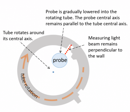 The probe simply needs to be lowered into the tube at a constant distance from the tube’s ID surface.